The Short Version
- For far too long I started Jenny with a hotwire from the alternator to the coil, and pulled it off again to stop the engine.
- I ran a new ignition-live wire from the fuse box to the engine bay, and fitted two relays: one for the coil and one for the electric fuel pump.
- She now starts on the key. 🎉
- But she wouldn't stop on the key. A small voltage feeding back holds the relay on. My workaround: flash the high beams. The proper fix is a diode.
Why I Needed to Sort It
Jenny has always had intermittent ignition problems. It's been on the "need to do" list for ages, and I just hadn't got round to it.
Instead, for an embarrassingly long time, I ran a hotwire from the alternator to the coil. Every time I wanted to start her, I opened the engine lid and connected it. Every time I wanted to stop, I opened the lid again and disconnected it. Not ideal at a petrol station.
Then I fitted an electric fuel pump (a Facet, about £75 on eBay as of November 2026), and the hotwire went from annoying to a genuine problem. With a permanent live in the system, the pump could keep pumping when it shouldn't. Not good practice at all!
Somewhere in Jenny's 50-year history, someone fitted an alarm and immobiliser. It didn't work when I bought her in 2017, and all that was left was a nest of wires behind the fuse box. I've since had a good tidy up and removed them. That made this job a lot easier.
So the fix I wanted was simple: a new ignition-live wire, with relays for the coil and the fuel pump. Two separate relays mean that if something goes wrong in future, I can tell which circuit it is.
Useful reading: Just Kampers have a good video on setting up a new ignition-live relay. I used it alongside a wiring diagram from the Haynes manual for the technical side.
How a Relay Works (In Plain English)
This was the bit that made everything click for me. A relay is a switch that's operated by electricity rather than your finger. A small current switches a big one.
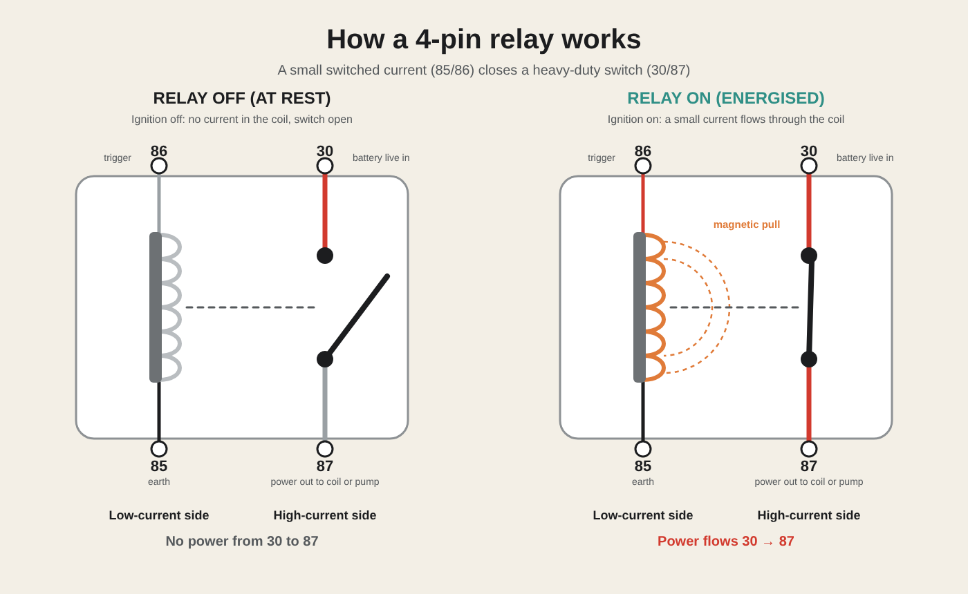
Left: ignition off, switch open. Right: ignition on, the coil becomes a magnet and pulls the switch closed.
Inside the relay there are two separate circuits:
- The control side (low current): pins 85 and 86. This is a small coil of wire.
- The load side (high current): pins 30 and 87. This is a heavy-duty switch.
Here's what happens:
- Ignition off: no current in the coil, so the switch stays open. No power gets from 30 to 87.
- Ignition on: a tiny current flows through the coil, from 86 to 85.
- The coil becomes a magnet and pulls the switch closed.
- Power flows straight from the battery (30) to whatever you're powering (87). On Jenny, that's the coil or the fuel pump.
- Ignition off again: the magnet switches off, a spring pulls the switch open, and the power stops. In theory… (more on that later!)
The four pins
| Pin | What it does | On Jenny it goes to |
|---|---|---|
| 85 | Coil earth | Chassis earth |
| 86 | Coil trigger (positive) | The new ignition-live wire |
| 30 | High-current power in | Fused battery live |
| 87 | High-current power out | Coil + (relay 1) or fuel pump + (relay 2) |
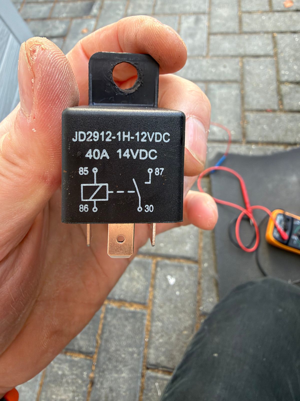
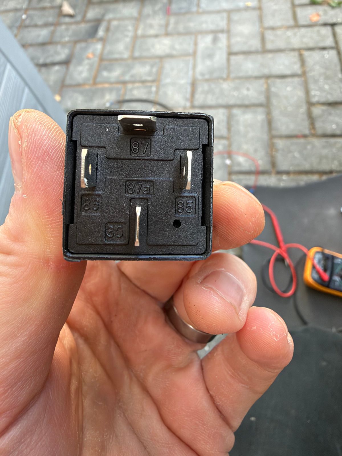
Most relays have the pin diagram printed on the side and the numbers moulded next to each pin underneath. Check yours before you crimp anything.
Tip: you'll find some diagrams online with 85 and 86 swapped. On a basic relay it doesn't matter, but some relays have a built-in diode or resistor on the coil side, and then it does. 86 to the trigger, 85 to earth is the convention I followed.
What I Used
Everything I bought for this job, plus the tools that made it easier. These are affiliate links, which help keep this site running at no extra cost to you.
Parts
- 12V 4-pin relays — I used two: one for the coil, one for the fuel pump.
- Inline fuse holders — I used 10A fuses on the trigger wire and each battery feed.
- Automotive wire — for the new ignition-live run from the fuse box to the engine bay.
- Electrical tape — to keep everything tidy.
- Crimp connectors — spade terminals to fit the relay pins.
- Cable ties — for securing the new wire along the chassis.
Tools
- Multimeter — essential for finding a true ignition live.
- Wire strippers and crimping tool
- Test light — handy for quick checks.
- Haynes manual — for the wiring diagram.
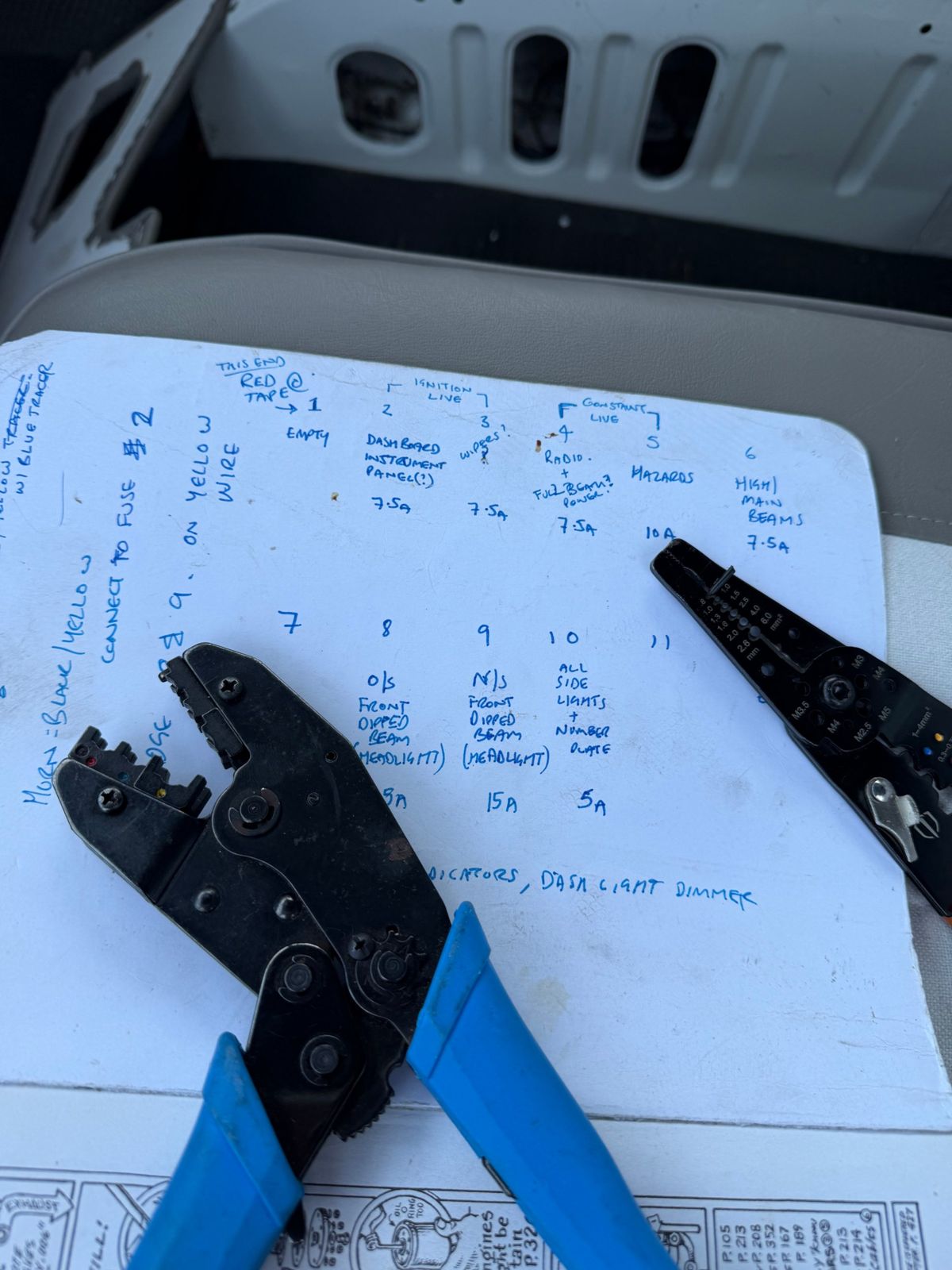
A decent crimper and wire strippers make all the difference to how neat (and reliable) the connections are.
How Jenny Is Wired Now
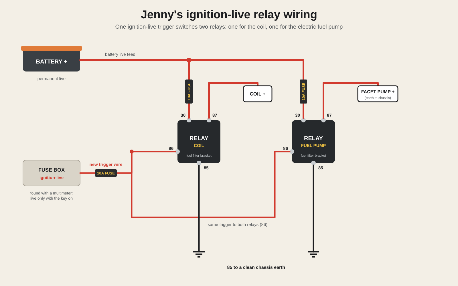
One fused ignition-live trigger switches both relays. Each relay takes a fused battery live in (30) and sends it out (87) to the coil or the fuel pump.
How I Did It, Step by Step
Step 1: Make up the new wire
I made up a new length of automotive wire, long enough to run from the fuse box at the front to the engine bay at the back, and added inline fuses (10A) just to be sure.
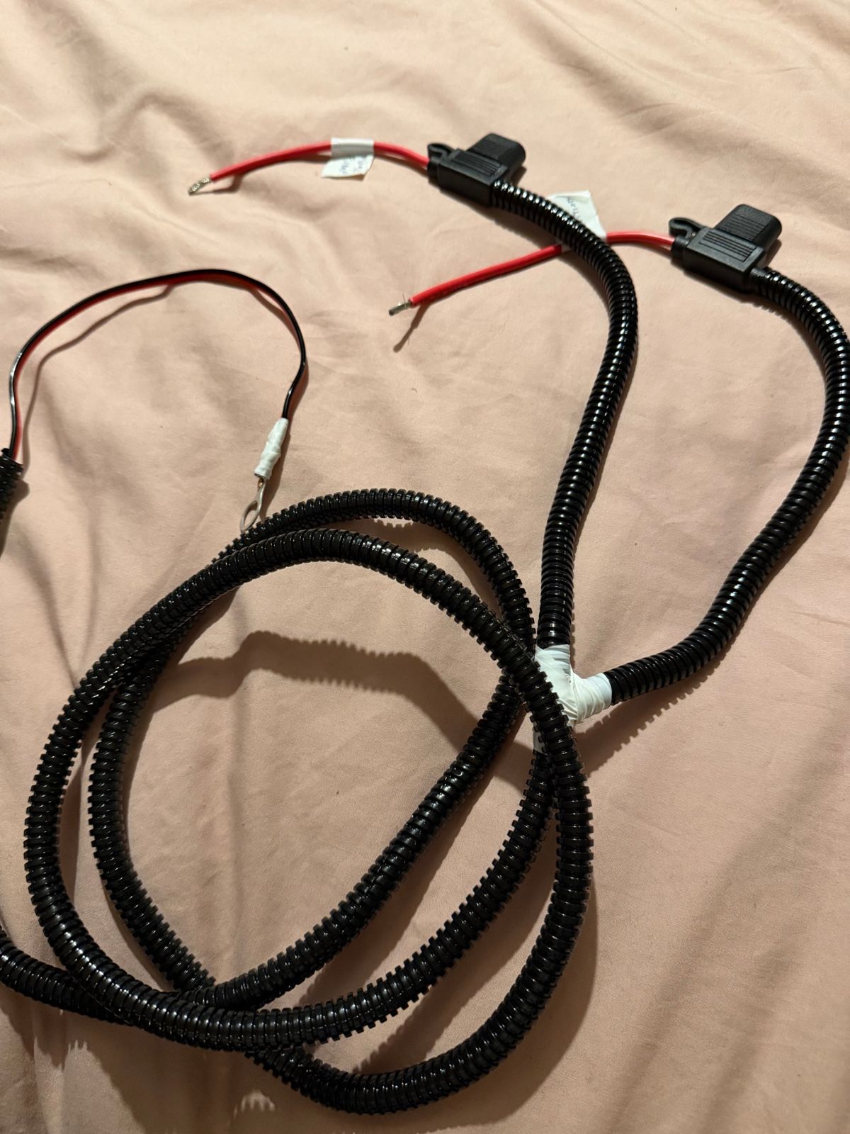
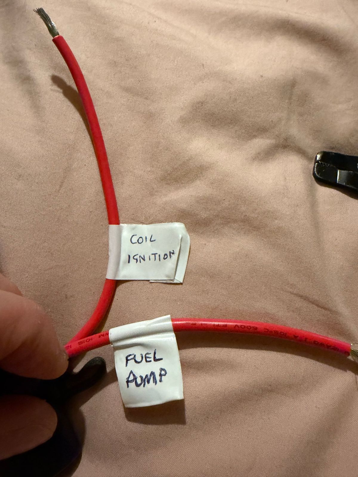
The new harness with its inline fuse holders, and the two output wires labelled up. Label everything!
Step 2: Find an ignition live
This is where the multimeter earns its keep. You're looking for a terminal at the fuse box that's live with the key on, and dead with the key off.
My fuse box was a bit of a mess before I removed all the old alarm wiring. It's much tidier now, though still not stock or perfect! Take your time here and test with the key on and off.
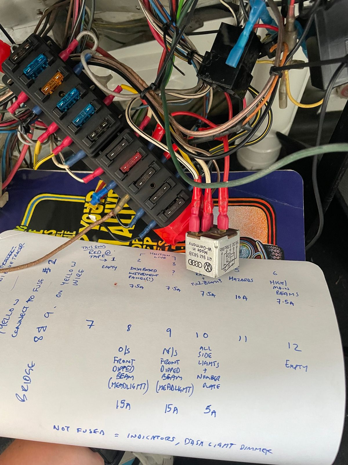
My fuse box, mid tidy-up, with the map I drew of what each fuse does. 50 years of wiring history in one photo.
Step 3: Run the wire to the engine bay
I connected the new wire to the ignition live and ran it through the chassis back to the engine bay, securing it with cable ties as I went. Before going any further, I tested it at the engine end: live with the key on, dead with the key off.
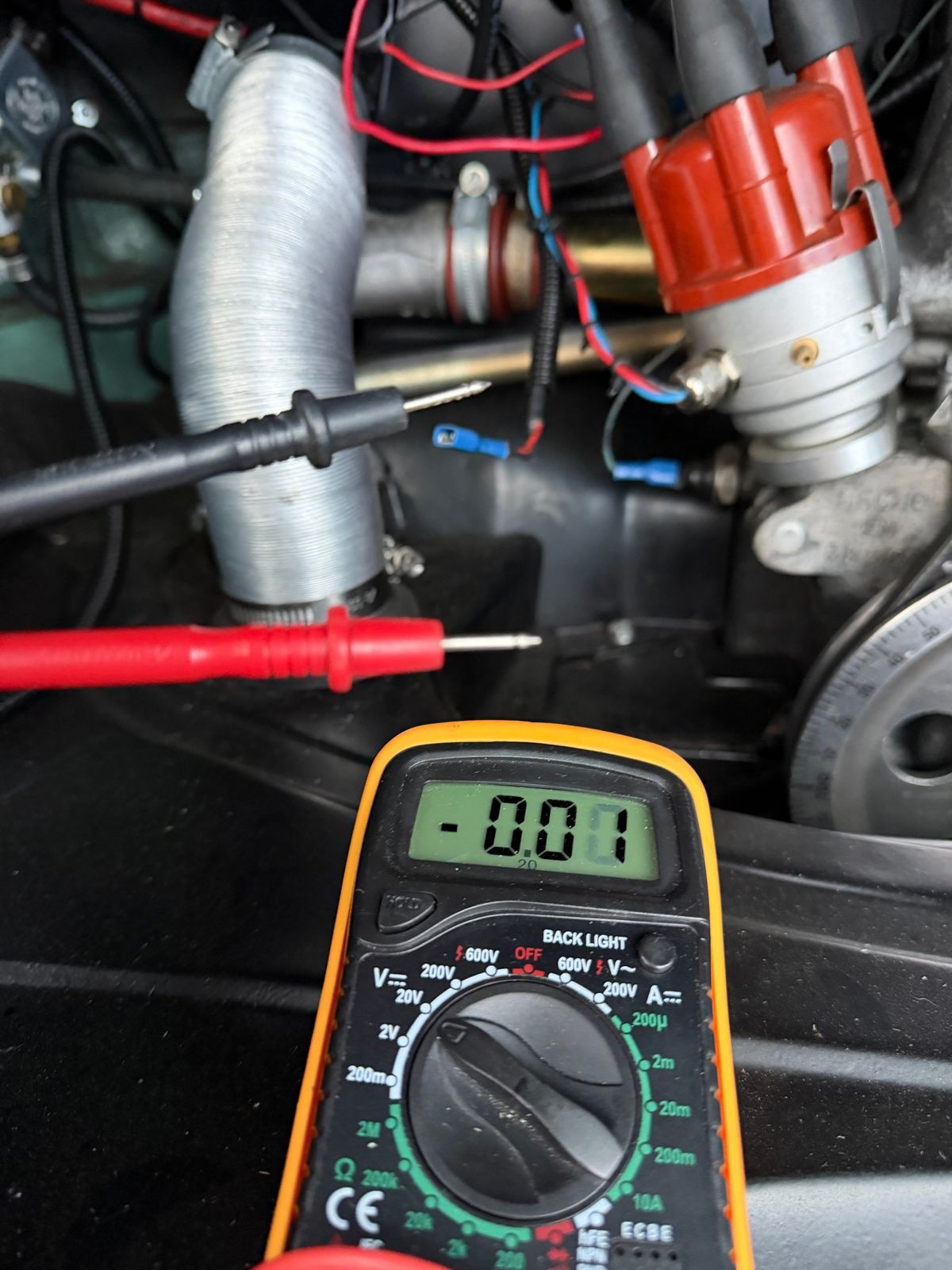
Testing the new wire at the engine end. With the key off it should read zero, as here. With the key on you want around 12V.
Step 4: Mount the relays
The two relays fitted perfectly on the fuel filter bracket. Nice and tidy, and easy to get at if I ever need to swap one.
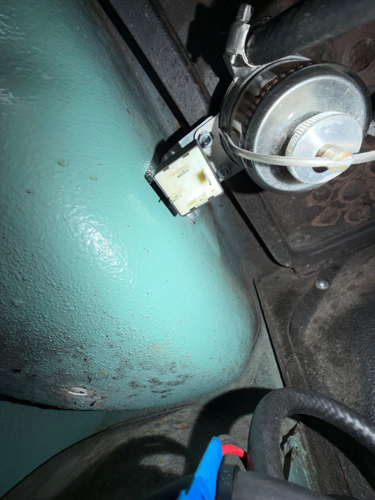
The fuel filter bracket turned out to be the perfect home for the relays.
Step 5: Wire the relays
Following the pin layout above:
- Relay 1 (coil): 85 to earth, 86 to the new ignition-live wire, 30 to a fused battery live, 87 to the coil.
- Relay 2 (fuel pump): exactly the same, except 87 goes to the fuel pump.
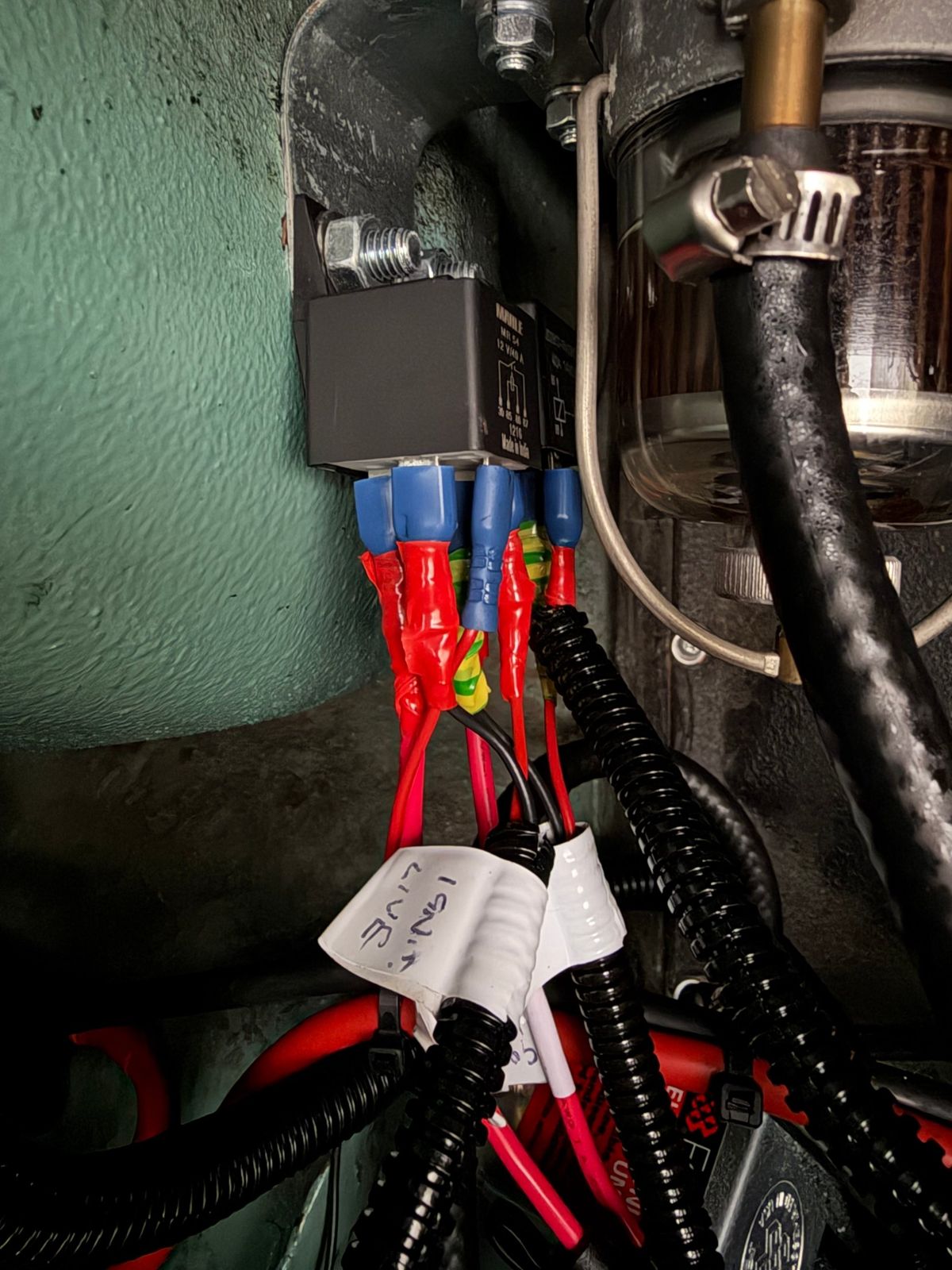
Both relays wired in, with the earths on the green and yellow wires and everything labelled.
Step 6: Test it
The proof was in the testing, and it worked! Jenny now starts on the key. No more opening the engine lid to connect a hotwire. A proper "why didn't I do this years ago" moment.
Just One Thing… She Won't Switch Off!
I turned the key off to stop the engine and… Jenny carried on running. Aaaaaaargh.
After more googling and reading, it turns out this is a common problem. Even with the key off, a small voltage is feeding back into the ignition-live circuit from somewhere else. A relay only needs a tiny current to stay closed, so that trickle is enough to keep the coil powered and the engine running.
On many classic VWs, the usual suspect is the charge warning light circuit: once the alternator is spinning, it can feed a little voltage back through the warning light into the ignition circuit. I haven't proved that's the source on Jenny yet.
My workaround: flash the high beams
The most common workaround I found was to switch on another load on the same fuse, usually the high beams. That soaks up the stray voltage, the relay drops out and the engine stops.
That's exactly what works on Jenny. I turn the key off, give the high beams a flash, and she stops. I've grown to quite like it! But it is a workaround, not a fix, so make sure anyone else who drives your van knows about it.
The proper fix: a diode
The proper fix is to fit a diode. A diode works like a one-way valve for electricity: current can flow through it one way, but not back the other. Fitted in the right place, it stops the stray voltage feeding back, so the relay drops out when you turn the key off.
Where the diode goes depends on where the feedback is coming from. If it's the warning light circuit, that's where it goes. This one is a job for another day, and I'll update this post when I've done it.
What I'd Tell Myself Before Starting
- Tidy the fuse box first. Removing the old alarm wiring made finding a clean ignition live so much easier.
- Test with the key on and off before you connect anything. A feed that's live all the time isn't an ignition live.
- Use two relays, not one. If the coil or the pump plays up, I know which circuit to look at.
- Fuse everything. The trigger wire and both battery feeds.
- Expect the run-on problem and plan for a diode from the start.
Common Questions
Why put the coil on a relay?
A relay lets a small ignition-live wire switch a heavy-duty feed straight from the battery. The coil gets a clean, full-voltage supply, and the old ignition switch and wiring only carry a tiny trigger current.
Which relay pin goes where?
On a standard 4-pin relay: 85 goes to earth, 86 to the ignition-live trigger, 30 to a fused battery live, and 87 out to the coil or fuel pump.
Why won't my engine switch off after fitting a relay?
A small voltage is feeding back into the ignition-live circuit and holding the relay closed. On many classic VWs this comes back through the charge warning light circuit once the alternator is spinning. Switching on another load on the same fuse can pull it down. The proper fix is a diode, which only lets current flow one way.
Do I need fuses on the new wiring?
Yes. I used 10A fuses on the trigger wire and each battery feed. Choose fuse ratings to suit the cable and what it powers, and check with an auto electrician if you're unsure.
🔧 Related Guides
- ⛽ Electric Fuel Pump for a VW Bay Window — the job that made this one essential
- 🔋 Leisure Battery & Split Charge Relay — a different kind of relay, for charging
- 🧰 VW Camper Breakdown Kit — what I carry, including spare fuses and relays
- ⚙️ Complete 1600cc Engine Rebuild